Using a PmodESP32 WiFi Module with AT Commands
Goal
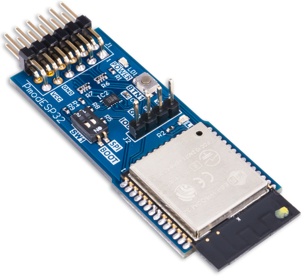
The goal is to start using a Digilent Pmod ESP32 module with AT commands.
Hardware Requirements:
- Digilent Pmod ESP32
- A USB to UART converter
- A good stable 3.3V supply with at least 500mA current.
Software Requirements:
- I will use Cursor with Python installed, but any command prompt will do.
- A Serial monitor program, such as Hercules, PuTTY, or Arduino IDE serial monitor
Challenge
The default Firmware on the PmodESP32 module uses USRT0 for logging, and listens to UART1 for AT commands. But UART1 is not exposed to Pmod pins, so you cannot work with it until you change the default Pmod pins and reflash the chip.
Step 0: Prepare the environment and necessary files
- Open a new fresh directory in Cursor. Download the suitable firmware from this link: https://docs.espressif.com/projects/esp-at/en/latest/esp32/AT_Binary_Lists/esp_at_binaries.html
- Download the recommended file from Section: ‘ESP32-WROOM-32 Series’.
- Extract it inside your Cursor folder.
- You will also need to modify the TX and RX pins for the AT commands. The default pins are not exposed to Pmod pins, so unless you are willing to solder wires to the ESP32 pins, you cannot use AT commands to communicate with your module. Fortunately Espressif provides an easy-to-use tool to configure UART on the module. The guide is here (for reference). I will tell you what to do myself. https://docs.espressif.com/projects/esp-at/en/latest/esp32/Compile_and_Develop/tools_at_py.html .
- Go to https://github.com/espressif/esp-at/blob/3c41c8fa/tools/at.py download the Raw File and save it under downloaded firmware inside ‘factory’ directory.
- Now we will create a virtual environment in Cursor to modify the UART on the firmware and flash the modified firmware to the chip. Inside Cursor terminal run:
python -m venv .venv
.venv\Scripts\activate
pip install esptool
pip install setuptools
Step 1: Hardware connections
| Pin on Pmod ESP32 Module | Name | Connect to |
| 5 Or 11 | GND | GND pin of UART to USB module GND pin of your 3.3V supply |
| 6 Or 12 | VCC | 3.3V supply |
| 2 Or RX pin on the 4-pin connector | Module RX (AT commands) | TX Pin of UART to USB module |
| 3 Or TX pin on the 4-pin connector | Module TX (AT Responses) | RX Pin of UART to USB module |
Step2: Prepare and flash the firmware
In Cursor terminal go inside the factory folder of the downloaded firmware. You should see the following files:
at.pythat you downloaded in Step 0.factory_WROOM-32.binwhich is included in the original firmware downloaded is Step 0.
Activate the virtual environment if it is not already activated:
python -m venv .venvNow modify the firmware:
python at.py modify_bin --tx_pin 1 --rx_pin 3 --cts -1 --rts -1 --in factory_WROOM-32.bin --out factory_WROOM32_UART0.binIf everything is fine you should see a file named factory_WROOM32_UART0.bin created in that folder.
Now flash the modified firmware to the chip:
- Use Hardware Manager on your PC to see the COM port associated with your UART to USB converter.
- Move the small DIP switch BOOT switch to ON position
- Make sure the small DIP switch SPI is in OFF position
- Reset the module by pressing the BTN1 push button on it.
- Type in the following command making sure you replace COM13 with your UART to USB converter’s COM port:
python -m esptool --chip esp32 --port COM13 --baud 921600 write_flash 0x0 factory_WROOM32_UART0.binIf everything works fine, you should see something like this:
esptool v5.2.0
Connected to ESP32 on COM13:
Chip type:          ESP32-D0WD-V3 (revision v3.0)
Features:           Wi-Fi, BT, Dual Core + LP Core, 240MHz, Vref calibration in eFuse, Coding Scheme None
Crystal frequency:  40MHz
MAC:                94:e6:86:0d:d5:f8

Stub flasher running.
Changing baud rate to 921600...
Changed.

Configuring flash size...
Flash will be erased from 0x00000000 to 0x003fffff...
Wrote 4194304 bytes (1006328 compressed) at 0x00000000 in 23.3 seconds (1439.1 kbit/s).
Hash of data verified.

Hard resetting via RTS pin...
Testing the module
Open a terminal with Baud rate 115200. Put both DIP switches to OFF position and reboot the module by pressing the BTN1 push button. You should see something like this in your terminal:
ets Jul 29 2019 12:21:46

rst:0x1 (POWERON_RESET),boot:0x13 (SPI_FAST_FLASH_BOOT)
configsip: 0, SPIWP:0xee
clk_drv:0x00,q_drv:0x00,d_drv:0x00,cs0_drv:0x00,hd_drv:0x00,wp_drv:0x00
mode:DIO, clock div:2
load:0x3fff0030,len:5168
load:0x40078000,len:15896
load:0x40080400,len:4
ho 8 tail 4 room 4
load:0x40080404,len:3540
entry 0x400805f0
I (31) boot: ESP-IDF v5.4.1-643-g8ad0d3d8f2-dirty 2nd stage bootloader
I (31) boot: compile time Aug  1 2025 05:22:24
W (31) boot: Unicore bootloader
I (34) boot: chip revision: v3.0
I (37) boot.esp32: SPI Speed      : 40MHz
I (41) boot.esp32: SPI Mode       : DIO
I (44) boot.esp32: SPI Flash Size : 4MB
I (48) boot: Enabling RNG early entropy source...
I (52) boot: Partition Table:
I (55) boot: ## Label            Usage          Type ST Offset   Length
I (61) boot:  0 phy_init         RF data          01 01 0000f000 00001000
I (68) boot:  1 otadata          OTA data         01 00 00010000 00002000
I (74) boot:  2 nvs              WiFi data        01 02 00012000 0000e000
I (81) boot:  3 at_customize     unknown          40 00 00020000 000e0000
I (87) boot:  4 ota_0            OTA app          00 10 00100000 00180000
I (94) boot:  5 ota_1            OTA app          00 11 00280000 00180000
I (100) boot: End of partition table
I (104) esp_image: segment 0: paddr=00100020 vaddr=3f400020 size=13db0h ( 81328) map
I (139) esp_image: segment 1: paddr=00113dd8 vaddr=3ff80064 size=0001ch (    28) load
I (139) esp_image: segment 2: paddr=00113dfc vaddr=3ffbdb60 size=055c8h ( 21960) load
I (151) esp_image: segment 3: paddr=001193cc vaddr=40080000 size=06c4ch ( 27724) load
I (162) esp_image: segment 4: paddr=00120020 vaddr=400d0020 size=13524ch (1266252) map
I (593) esp_image: segment 5: paddr=00255274 vaddr=40086c4c size=14b24h ( 84772) load
I (626) esp_image: segment 6: paddr=00269da0 vaddr=400c0000 size=00064h (   100) load
I (640) boot: Loaded app from partition at offset 0x100000
I (640) boot: Disabling RNG early entropy source...
I (889) at-init: at param mode: 1

ready
Now, make sure that you send both CR (carriage return) and NL (new line) after each line. Send AT Command. The module should respond with OK.
Useful AT commands
If you have reached here, congratulations! Your Module is alive and responding to AT commands. A good guide for AT commands for this module can be accessed inside your downloaded firmware folder ([ESP32-AT][v4.1.1.0]User-Guide.pdf). But here I will list a few basic commands that let you start using your module.
SoftAP vs Station modes
By default the ESP32 module starts with SoftAP mode where it can act as a router and have other devices connected to it. You can change it to Station mode where it can connect to other WiFi networks. Type in:
AT+CWMODE?The response tells you the current mode, 1 is Station mode and 2 is the SoftAP mode (default). If you want to activate the station mode type: AT+CWMODE=1
Then you can see a list of available WiFi networks using:
AT+CWLAP
The response will be something like:
+CWLAP:(3,"<NW_SSID1>",-25,"<MAC ADDR>",6,-1,-1,4,4,7,0)
+CWLAP:(3,"NW_SSID2",-63,"<MAC ADDR>",6,-1,-1,4,4,7,0)
+CWLAP:(4,"SFR-f800",-68,"b8:d9:4d:09:f8:06",1,-1,-1,5,3,7,1)
+CWLAP:(3,"Freebox-16BD30",-77,"3a:07:16:0c:bd:64",6,-1,-1,4,4,7,1)
Where you can see information such as encryption type, signal strength, channel, ….
Connect to a WiFi Network and Fetch a website
AT+CWMODE=1
AT+CWJAP="<SSID>","<your_password>"
You should see:
WIFI CONNECTED
WIFI GOT IP

OK
Then you can do a ping test an address:
AT+PING="8.8.8.8"
+PING:44

OK
Where the number is ping time in milliseconds. You can also fetch a webpage:
- Close any TCP connections if they exist:
AT+CIPCLOSEIf there are open TCP connections, this will close them, otherwise you will receive an ERROR response.
- Open a new connection to the desired website url:
AT+CIPSTART="TCP","example.com",80- Instruct the module to send the request. Here, you have two options: You van either A) Tell the module the number of bytes you will send, or B) Terminate your transmissions with a CTRL+Z (ASCII code 26) character. We will use the first approach here:
- Wait for the
>prompt. Then Enter this command. It is important that the$0D$0Acharacters would be sent exactly as CR and NL characters:
GET / HTTP/1.1$0D$0AHost: example.com$0D$0AConnection: close$0D$0A$0D$0A- The response if everything goes according to the plan would be:
Recv 56 bytes

SEND OK

+IPD,837:HTTP/1.1 200 OK
Date: Fri, 17 Apr 2026 19:38:58 GMT
Content-Type: text/html
Transfer-Encoding: chunked
Connection: close
Server: cloudflare
Last-Modified: Tue, 14 Apr 2026 05:43:19 GMT
Allow: GET, HEAD
Accept-Ranges: bytes
Age: 8691
cf-cache-status: HIT
CF-RAY: 9edde4a149bd3cf2-CDG

210
<!doctype html><html lang="en"><head><title>Example Domain</title><meta name="viewport" content="width=device-width, initial-scale=1"><style>body{background:#eee;width:60vw;margin:15vh auto;font-family:system-ui,sans-serif}h1{font-size:1.5em}div{opacity:0.8}a:link,a:visited{color:#348}</style></head><body><div><h1>Example Domain</h1><p>This domain is for use in documentation examples without needing permission. Avoid use in operations.</p><p><a href="https://iana.org/domains/example">Learn more</a></p></div></body></html>

0


CLOSED
which is the returned page contents of www.example.com
In AP Mode, Create a Tiny TCP Server
Here we will activate the Access Point mode, connect to it using our phone, and fetch a dummy web page.
First let us activate the access point mode (remember: SoftAP mode, CWMODE=2):
AT+CWMODE=2
AT+CWSAP="ESP_TEST","12345678",5,3
This tells the module to create an Access Point with SSID ESP_TEST and password 12345678.
Now with your phone/computer you can connect to ESP_TEST network. You should see something like this in your terminal:
OK
+STA_CONNECTED:"<MAC_ADDR>"
+DIST_STA_IP:"MAC_ADDR>","192.168.4.2"
This tell us that a device with the showed MAC address has connected to the Access Point.
We will now create a tiny TCP server on port 80:
AT+CIPMUX=1
AT+CIPSERVER=1,80
Now we will connect to this tiny server using your phone/computer web browser. Open this url in the browser: http://192.168.4.1/
In your terminal, you will see a connection request:
+IPD,0,341:GET / HTTP/1.1
Host: 192.168.4.1
User-Agent: Mozilla/5.0 (Windows NT 10.0; Win64; x64; rv:149.0) Gecko/20100101 Firefox/149.0
Accept: text/html,application/xhtml+xml,application/xml;q=0.9,*/*;q=0.8
Accept-Language: en-US,en;q=0.9
Accept-Encoding: gzip, deflate
Connection: keep-alive
Upgrade-Insecure-Requests: 1
Priority: u=0, i
Now we will manually send a response using your terminal:
AT+CIPSEND=0,101Make sure that you send it with CR and NL characters at the end. This will tell the module that we are going to respond to client #0 with a 101 character length response. Now the actual response (without any line ending at the end):
HTTP/1.1 200 OK$0D$0AContent-Type: text/plain$0D$0AContent-Length: 17$0D$0AConnection: close$0D$0A$0D$0AHello from ESP32!Make sure that all $0D$0A are sent as a CR and NL characters. If everything works fine, your browser should show a Hello from ESP32! message!