Radar-Based Vehicle Speed Detection
Hardware and DSP implementation of a Doppler radar speed measurement system using the Innosent IVQ-3005 sensor and TI F28M35 processors.
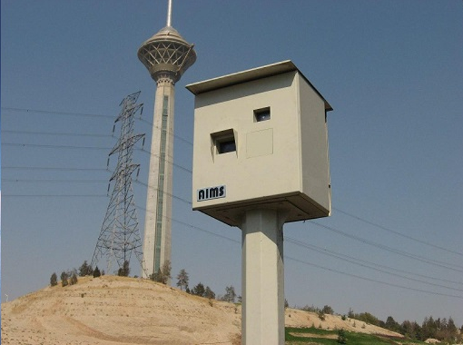
Overview
This system measures vehicle speed using the analog mixer output of a microwave Doppler radar sensor.
The signal is digitized and processed using real-time FFT analysis on a TI F28M35 DSP to determine the Doppler frequency shift produced by moving vehicles. I designed the complete hardware platform and implemented the embedded signal-processing firmware. Speed measurements are transmitted over LAN to a host computer, where they are correlated with camera-based vehicle identification before issuing enforcement actions.
System Architecture
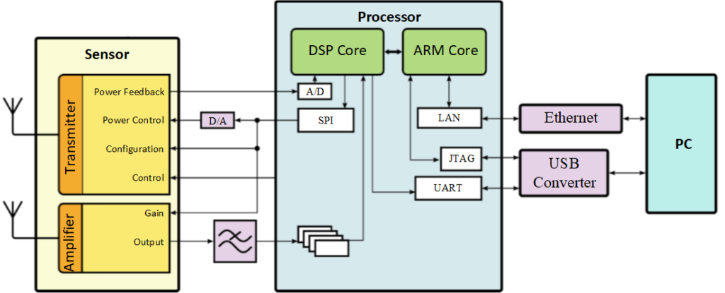
The system is built around an Innosent IVQ-3005 Doppler radar front end, whose analog mixer output contains the frequency information associated with the target’s radial speed. This signal is conditioned and digitized before being processed by a TI F28M35 processor. The embedded firmware performs real-time FFT analysis to detect the dominant Doppler component and estimate vehicle speed. The resulting measurements are then transmitted over LAN to a host computer, where they are combined with camera-based vehicle identification and verification software.
Signal Processing Principle
Vehicle speed is measured using the Doppler effect. When the microwave signal transmitted by the radar is reflected by a moving vehicle, the frequency of the returned signal is shifted proportionally to the vehicle’s radial velocity.
Inside the radar module, the transmitted and received signals are mixed together, producing a low-frequency analog signal whose dominant frequency corresponds to the Doppler shift.
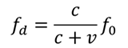
where is the Doppler frequency shift, is the radial velocity of the target, and is the frequency of the transmitted RF signal.
In the implemented system, the analog mixer output of the radar module is digitized and analyzed using real-time Fast Fourier Transform (FFT) processing on the DSP core of the TI F28M35 processor. The FFT identifies the dominant frequency component in the signal spectrum, which corresponds to the Doppler frequency produced by the moving vehicle. Once the Doppler frequency is determined, the vehicle speed can be computed directly from the radar wavelength.
In addition to speed measurement, the system also performs vehicle position estimation. This is achieved using frequency-shift ranging techniques in which the radar transmits two closely spaced frequencies and analyzes the resulting phase or frequency relationship in the received signal. By processing these signals, the system can estimate the distance to the detected vehicle along the monitored lane.
Distance estimation plays an essential role in the overall enforcement system. By determining the vehicle’s position within the radar field of view, the system can associate the measured speed with the correct vehicle captured by the camera. The radar therefore provides both speed and positional information, allowing the host computer to reliably match the radar measurement with the license plate recognized by the OCR subsystem before enforcement actions are issued.
Hardware Design
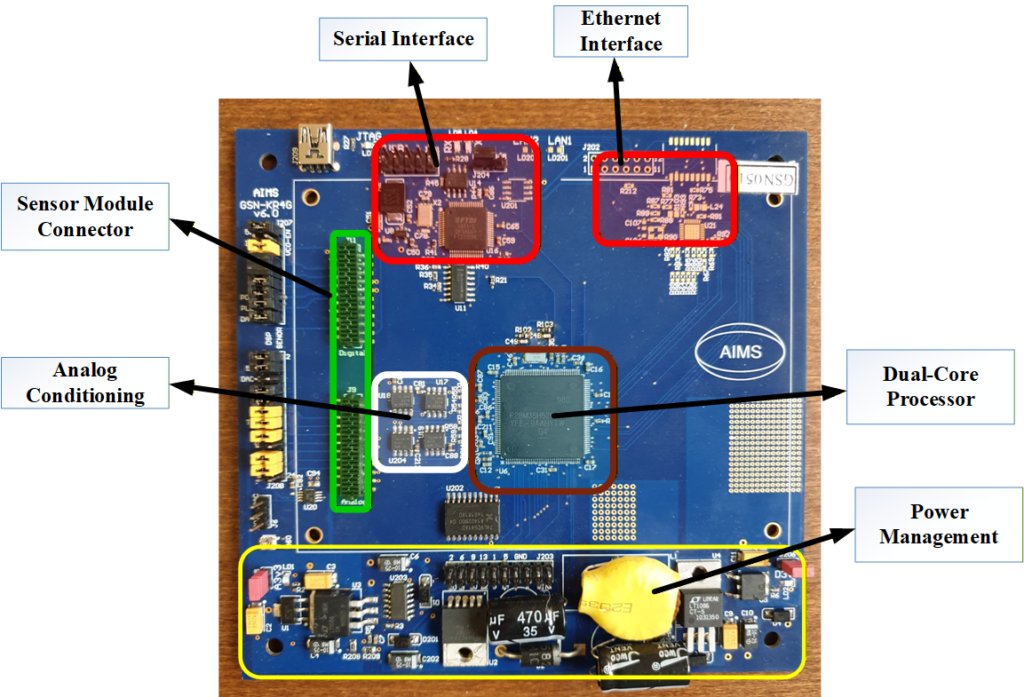
The radar processing unit was implemented on a custom six-layer PCB designed in Altium Designer. The stack-up consisted of top and bottom signal layers, two internal signal routing layers, and two internal power planes used for power distribution and grounding. This multilayer structure provided controlled routing for high-speed digital signals while maintaining good power integrity and low noise in the analog signal paths.
The radar module provides an analog mixer output containing the Doppler information. This signal is conditioned using a simple analog front-end consisting of an operational amplifier stage followed by an RC filter before being sampled by the internal ADC of the TI F28M35 processor.
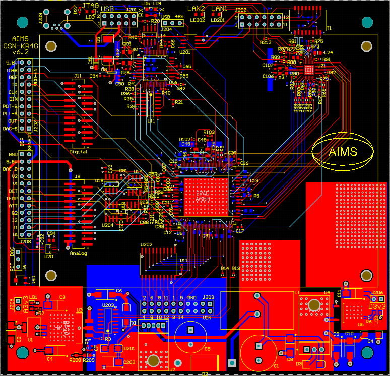
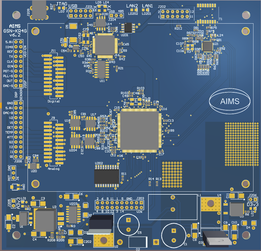
The board integrates the radar interface, analog conditioning circuitry, the TI F28M35 dual-core processor, and the required communication interfaces. The processor combines a C28x DSP core for real-time signal processing and an ARM Cortex-M3 core used for system control and communication. Care was taken during layout to separate sensitive analog sections from digital processing and communication circuitry in order to minimize interference and ensure reliable signal acquisition.
The resulting measurements are transmitted to the host computer through the network interface, where they are combined with camera-based vehicle identification and license plate recognition.
Embedded Software
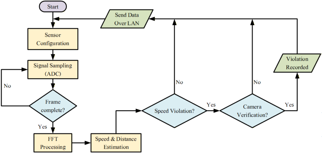
The embedded software was primarily implemented on the DSP core of the TI F28M35 processor. The DSP is responsible for the entire signal acquisition and processing pipeline, including ADC sampling, FFT computation, target detection, and speed estimation. The ARM Cortex-M3 core is used mainly for system management tasks such as LAN communication, watchdog supervision, and memory management.
The radar IF signal is sampled using the internal ADC with a sampling period of approximately 17 µs. Samples are collected into frames of 1024 points and processed using frame-based FFT analysis. ADC acquisition is interrupt-driven and uses DMA transfers to move data into memory with minimal CPU overhead. Timer interrupts coordinate the processing pipeline and ensure deterministic real-time operation.
The signal processing algorithm identifies spectral peaks corresponding to Doppler components produced by moving vehicles. Up to 50 targets can be detected within a single frame. Additional processing is used to compensate for phase differences between samples acquired during the high and low frequency states of the FSK radar signal, enabling accurate distance estimation alongside speed measurement.
Processed measurements are transmitted to the host computer using UDP over Ethernet through the lwIP network stack. The host software then correlates the radar measurements with camera-based vehicle identification and license plate recognition before enforcement actions are issued.
My Role
I was responsible for the complete design and implementation of the radar processing unit, including both hardware and embedded software. This involved the schematic design and PCB layout of the six-layer processing board in Altium Designer, integration of the radar front-end interface, and development of the analog signal conditioning circuitry used to prepare the radar mixer output for digitization.
On the software side, I implemented the full embedded signal-processing pipeline on the TI F28M35 processor. This included ADC acquisition using interrupt-driven sampling with DMA transfers, frame-based FFT processing, multi-target detection, and the algorithms used to estimate vehicle speed and distance from the radar signals.
I also developed the embedded networking interface used to transmit measurements to the host computer via UDP over Ethernet using the lwIP stack, and implemented the supporting system software for communication, memory management, and watchdog supervision.
The camera subsystem, license plate recognition, and host computer software responsible for correlating radar measurements with vehicle images were developed by other members of the project team.