LoRa Modulation
Contents
Part 3 — LoRa Basics
Before going into the details of LoRa modulation, it is important to clarify a common source of confusion: LoRa and LoRaWAN are not the same thing.
- LoRa refers to the physical layer, that is, the modulation technique used to transmit signals over the air.
- LoRaWAN is a communication protocol built on top of LoRa, defining how devices communicate, authenticate, and exchange data within a network.
In this page, we focus only on LoRa as a modulation technique, independently of any network protocol.
Chrip: LoRa’s fundamental waveform
A chirp is a signal whose instantaneous frequency increases or decreases over time. In other words, instead of oscillating at a fixed frequency, the signal continuously sweeps through a range of frequencies.
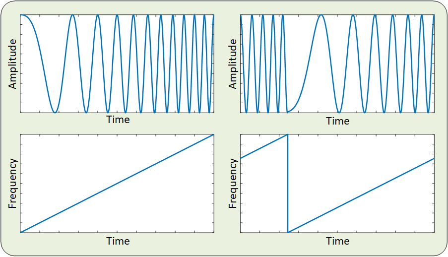
Figure 1 — Examples of chirp signals
In Figure 1, we see two examples of chirp signals. On top we have the signal in time domain, while bottom plots are what we call “Frequency Map” which shows the instantaneous frequency of the sine wave (not to be confused with frequency domain representation of the signal).
The signals shown in Figure 1 are called up chirps because their frequency increases over the time. If the frequency of a chirp decreases over the time, it is called a down chirp.
LoRa modulation (encoding)
In a digital communication system, information is sent one symbol at a time. In some cases, each bit is encoded in a symbol. This is called a binary communication system. An example would be BPSK, where 0’s and 1’s are sent using sine waves of identical frequencies and amplitudes, but with a phase difference of 180°. A more general case would be -ary communication systems, where the transmitter sends bits at a time. Since each sequence of bits can produce distinct outcomes, the symbols will be selected from an alphabet consisting of symbols. LoRa is another example of an -ary communication symbols where a group of bits are transmitted as one symbol. We will talk about SF and what it represents in the next chapter of this tutorial.
In LoRa, each symbol is a time-shifted up chirp, where the signal sweeps across the entire allocated bandwidth during each symbol period starting at a frequency that depends on the transmitting symbol. Once the upper limit of the bandwidth is reached, the frequency wraps around and continues from the lower limit.
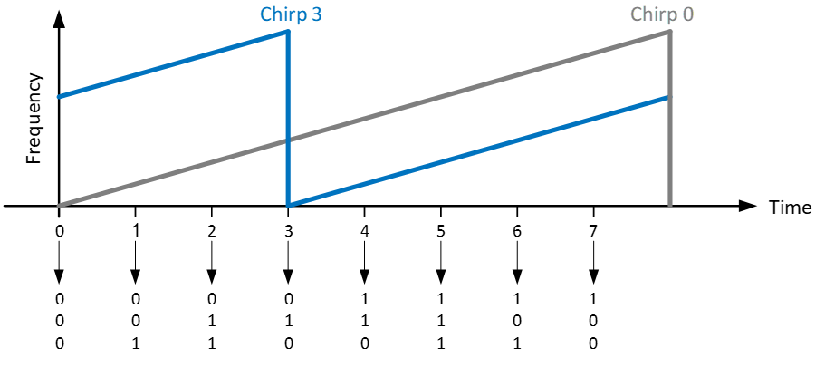
Figure 2 — LoRa modulation by cyclically shifting the starting position of an up-chirp. In this example three bits are transmitted at a time. Therefore we have a to total of eight different symbols. Note that Gray Coding is used so that two consecutive symbols differ only in one bit.
Every LoRa symbol uses the same chirp. The transmitted information is contained only in the position at which the chirp begins within its cyclic frequency sweep. So a LoRa receiver has to look at the received signal, and try to infer the starting frequency (i.e. the time shift) of the transmitted signal. This is what we cover next.
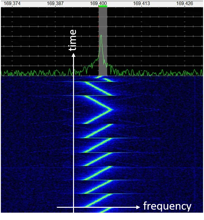
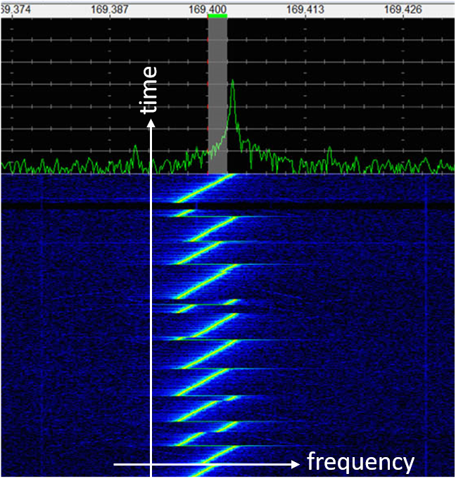
Figure 3 — Real LoRa signals. Left spectrogram is the start of frame. We can see preamble (up-chirps, i.e. frequency increasing over time) and start frame delimiters (exactly 2.5 down-chirps, i.e. frequency decreasing over time). The right spectrogram shows a sample LoRa payload. We can see the time-shifted up-chirps. The amount of the cyclic shift, is determined by the transmitting symbol.
LoRa demodulation (decoding)
At first glance, this appears to be a difficult problem. Every LoRa symbol is almost identical, differing only by the starting position of the chirp. Measuring this starting position directly would be both complicated and sensitive to noise.
Fortunately, LoRa uses a much simpler and more elegant solution. In order to understand this approach we should note that if two sine waves are multiplied together, the resulting signal will contain sum and difference of the frequencies of the two signals:
Therefore, if an up-chirp with instantaneous frequency of is multiplied by a down-chirp with instantaneous frequency of , the resulting signal would contain both frequencies. The receiver effectively keeps the low-frequency (difference) term . This is the fundamental principle behind LoRa demodulation.
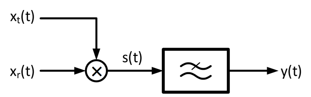
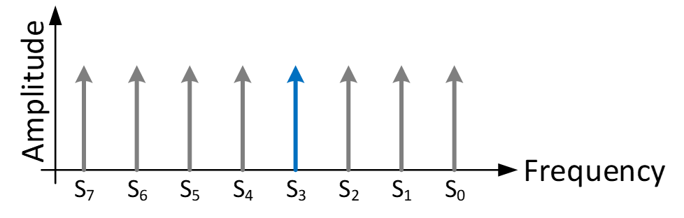
Figure 4 — Simplified block diagram of a LoRa receiver (left) and possible outcomes of the resulting signal in frequency domain (right). In this figure, is the received up-chirp that can be one of the possible symbols shown in Figure 2, is the reference down chirp, and is the filtered product output whose frequency domain representation is shown on the right.
The receiver multiplies the received LoRa signal by a reference down-chirp, then the output of the low-pass filter will be essentially a single-tone sine wave whose frequency depends only on the transmitted signal. For example, if the transmitted bits are 010, the corresponding frequency map will be the blue signal shown in Figure 2, called Chirp 3. Then low-pass-filtered product of Chirp 3 by the reference down-chirp, will be a sine wave with frequency of S3 in Figure 3.
This principle is illustrated in Figure 4.
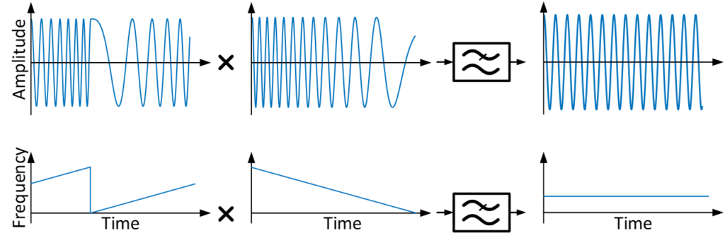
Figure 5 — The principle of LoRa demodulation: Multiplying the transmitted signal by a reference down-chirp, followed by a low-pass filter. The chirp dissapears.
After this, detecting the transmitted symbol becomes a simple frequency estimation problem. In practice, this is efficiently performed using a Fast Fourier Transform (FFT), where each possible symbol corresponds to one frequency bin.
Why is LoRa so resilient?
One natural question here is: That’s clever… but why go through all this trouble? There are far simpler modulation/demodulation schemes! In this subsection, we will try to answer this question.
Wideband transmission and narrowband interference
Because every chirp sweeps across the entire channel bandwidth, the transmitted energy is distributed over many frequencies rather than concentrated at a single carrier frequency. This makes the signal much less sensitive to narrowband interference. If an interfering transmitter occupies only a small portion of the spectrum, it affects only a small part of each chirp instead of disrupting the entire transmission.
Correlation-based detection and processing gain
Unlike conventional receivers that estimate the signal at a single frequency, a LoRa receiver compares the received waveform with a locally generated reference chirp. If the received signal matches the expected chirp, all parts of the waveform contribute coherently to the final decision. Random noise, on the other hand, has no chirp structure and therefore correlates poorly with the reference waveform. As a result, the useful signal is accumulated over the entire symbol duration, while the contribution of random noise is greatly reduced. This improvement in the effective signal-to-noise ratio after correlation is commonly referred to as the processing gain of the LoRa receiver.