LoRa Modulation
Contents
- Introduction
- Wireless Sensor Networks and LPWAN
- LoRa Basics
- LoRa Parameters
- Summary and Outlook
Part 4 — LoRa Parameters
So far, we have treated LoRa modulation as if every chirp had fixed characteristics. In practice, however, LoRa is highly configurable. A small number of physical-layer parameters determine how quickly the chirp sweeps, how long each symbol lasts, how much redundancy is added, and how much power is transmitted.
These parameters are not independent settings that can simply be maximized. Each one introduces a trade-off. A configuration that improves receiver sensitivity may also increase airtime. A configuration that increases data rate may reduce communication range. Higher transmit power may improve the link budget, but it also increases energy consumption and may be limited by regional regulations.
For this reason, choosing LoRa parameters is fundamentally an engineering problem. The appropriate configuration depends on the application, the propagation environment, the required reliability, the permitted latency, and the available energy source.
In this part, we will first examine what the main LoRa parameters physically mean:
- channel bandwidth,
- spreading factor,
- coding rate,
- carrier frequency,
- and transmit power.
We will then study how they affect the main performance characteristics of a LoRa link, including:
- data rate and airtime,
- noise immunity and interference resilience,
- receiver sensitivity and link budget,
- indoor and outdoor range,
- network capacity,
- and battery life.
The objective is not merely to learn that increasing the spreading factor improves range, or that increasing the bandwidth raises the data rate. We want to understand why these effects occur, and how the parameters interact when designing a real LoRa system.
Center frequency
In the previous page, we represented LoRa chirps as frequency sweeps between a lower and an upper limit. In a real radio transmission, however, this sweep does not start from zero frequency. It occupies a channel centred around an RF frequency, which we call the center frequency . For a channel bandwidth (BW), the chirp ideally sweeps between:
When it reaches one edge of this interval, it wraps around to the other, as we saw on the previous page.
LoRa modulation can operate across different RF bands, but the permitted frequencies depend on the country or region. Commonly encountered sub-GHz operating regions include:
- around 433 MHz in Europe and Middle East;
- 863–870 MHz in Europe;
- 902–928 MHz in North America;
Choosing a frequency range, not only affects propagation and link budget, but also entails different antenna designs. Higher frequencies experience more path loss than lower frequencies. However, in indoor situations, propagation depends strongly on wall materials, building geometry, antenna placement, polarization, multipath, and the presence of people and objects.
Another use of the center frequency, is to avoid interference. This can have a major effect if another transmitter uses the selected channel.
Spreading factor (SF)
This is probably the most important parameter of the LoRa modulation, because it directly affects the battery life and reliability of the communication.
On the previous page, we saw that LoRa represents each symbol using a cyclically shifted chirp. The spreading factor (SF) is the parameter that controls the time scale of that chirp. For a fixed channel bandwidth: A small SF produces a fast chirp, while a large SF produces a slower chirp. Each time SF is increased by one, LoRa doubles the symbol duration. Therefore, an SF8 chirp takes twice as long as an SF7 chirp, SF9 takes four times as long, and SF12 takes 32 times as long. This can be a source of confusion. For conventional spread spectrum communication schemes, spreading factor usually refers to spreading the spectrum or bandwidth of the signal. Here it refers to spreading the duration of the signal over time.
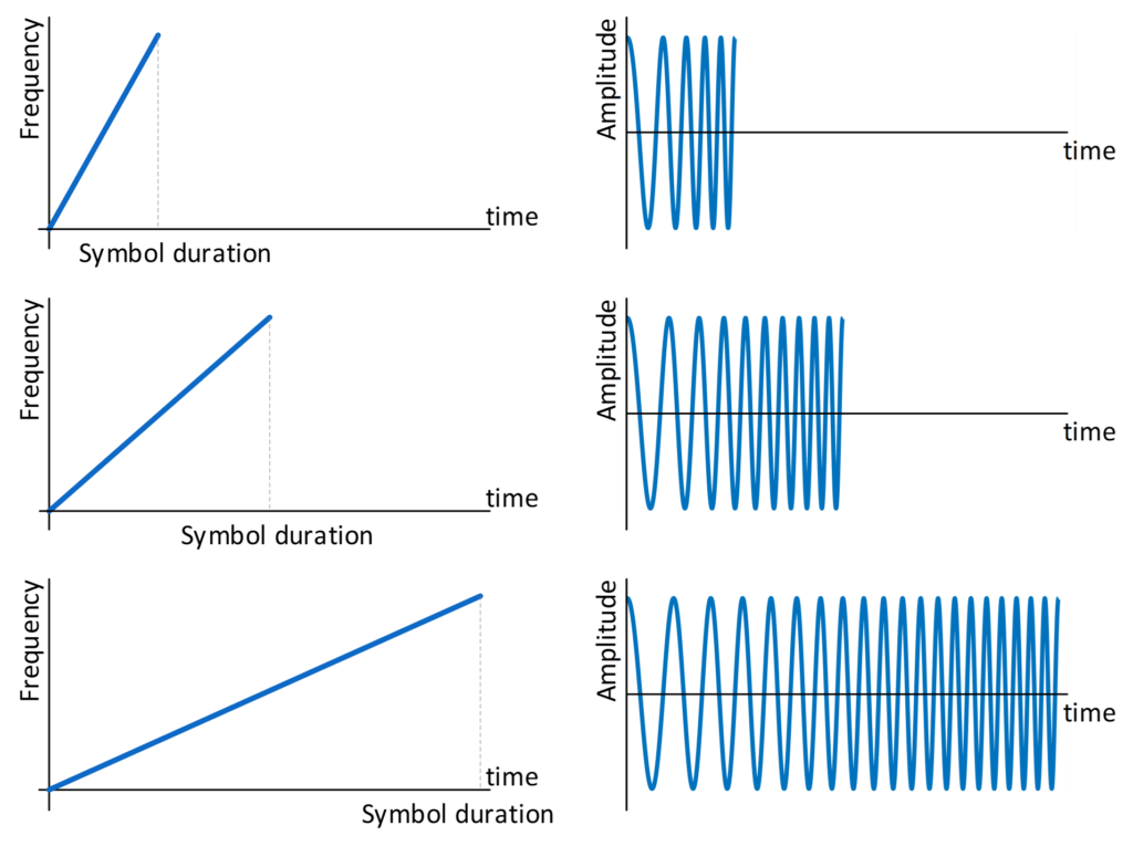
Figure 6 — Effect of spreading factor on chirp duration. For the same bandwidth, increasing SF slows the frequency sweep and increases the symbol duration.
This is the fundamental trade-off of LoRa communications: increasing SF improves sensitivity, but approximately doubles the symbol period at each step. This is because the slower chirp is observed over a longer period. As we saw on the previous page, the LoRa receiver does not make its decision from a single instantaneous measurement. It dechirps the received signal and accumulates information over the symbol before identifying the corresponding frequency bin. Increasing SF therefore provides a longer observation and correlation interval. The desired chirp structure contributes coherently over this interval, providing greater processing gain and allowing the receiver to recover signals at lower SNR. Semtech explicitly associates higher SF with increased processing gain and improved receiver sensitivity.
Semtech also made a design choice: For a spreading factor , the number of possible LoRa symbols is:
Remember that onn the previous page, we saw that a LoRa symbol is represented by a cyclically shifted chirp. The transmitted symbol determines where the chirp begins within its cyclic frequency sweep. The spreading factor determines how many different starting positions are available. This means that with SF=7, one chirp can represent one of 128 different symbol values, while with SF=12, it can represent one of 4096 values. Equivalently, each LoRa symbol carries SF bits of uncoded symbol information:
- SF7 → 7 bits per symbol
- SF8 → 8 bits per symbol
- …
- SF12 → 12 bits per symbol
This connects directly to the M-ary modulation concept introduced on the previous page.
Note that:
There is no fundamental property of chirps saying that a slower chirp must have more possible starting positions.
LoRa has been designed so that these properties are linked through SF: increasing SF both lengthens the symbol and increases the number of possible cyclic positions. The designers could, in principle, have defined a different modulation in which the chirp duration and the number of possible symbol positions followed different rules. The relationship above is therefore a property of LoRa modulation, not a universal law of chirp signals.
Let us normalize the duration of an SF7 symbol to 1. The we have the following table about LoRa bit rates for different spreading factors.
| Spreading factor (SF) | Possible symbols | Bits per symbol | Relative symbol duration | Relative raw information rate |
|---|---|---|---|---|
| 7 | 128 | 7 | 1 | 7 |
| 8 | 256 | 8 | 2 | 4 |
| 9 | 512 | 9 | 4 | 2.25 |
| 10 | 1024 | 10 | 8 | 1.25 |
| 11 | 2048 | 11 | 16 | 0.6875 |
| 12 | 4096 | 12 | 32 | 0.375 |
Thus, although an SF12 symbol contains more information, its much longer duration dominates. For fixed bandwidth, the uncoded raw information rate therefore follows the proportionality:
before coding and packet overhead are considered.
It is important to note that increasing SF does not change the way radio waves propagate. Walls do not become less attenuating, free-space path loss does not decrease, and the antenna does not become more efficient. Instead, the receiver becomes capable of correctly demodulating a weaker signal. The additional receiver sensitivity therefore provides more link-budget margin, which can be used to tolerate:
- greater outdoor path loss,
- walls and floors,
- shadowing and foliage,
- fading,
- or poorer antenna placement.
This is why higher SF is commonly associated with longer range even though the propagation channel itself has not changed. Semtech likewise recommends lower SF when little link budget is needed and higher SF for more distant nodes because of the additional processing gain and sensitivity.
The price of this additional sensitivity is airtime.
A higher-SF packet occupies the radio channel for much longer. Semtech’s example for an 11-byte payload at 125 kHz illustrates the effect clearly: its reported time on air increases from about 61 ms at SF7 to 371 ms at SF10.
Longer airtime generally means:
- more energy consumed for each transmission;
- longer occupation of the radio channel;
- greater probability of collisions in a busy network;
- and lower overall network capacity.
Therefore, the highest SF is not automatically the best SF.
A useful engineering rule is:
Use the lowest spreading factor that still provides sufficient link margin and reliable communication.
If SF7 already provides a robust link, moving to SF12 gains little but costs considerable airtime and energy. Conversely, if the link cannot reliably be closed at SF7, the additional processing gain of a higher SF may be well worth that cost.
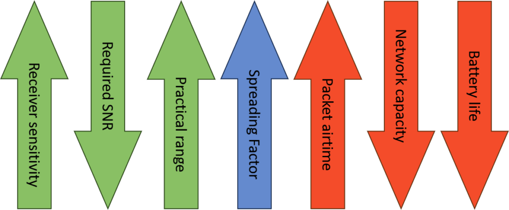
Figure 7 — Effect of increasing the spreading factor on other performance metrics of a LoRa communication system.
Channel bandwidth (BW)
The channel bandwidth is the frequency band swept by each LoRa chirp. For example, with a bandwidth of 125 kHz, the instantaneous frequency of the chirp moves across a 125 kHz-wide channel during one symbol period.